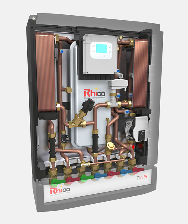
Ultra Lean Indirect Heat Interface Unit
The production of instantaneous DHW is via a stainless steel plate heat exchanger. The regulation of DHW temperature is electronic via a pressure independent control valve that also allows balancing of the HIUs within the system.
The heating is supplied via stainless steel plate heat exchanger. The regulation is made by a two-way valve (primary circuit) and the modulation of the secondary pump. The operation of the two-way valve maintains the secondary flow temperature at the set value. The speed of the secondary heating pump controls the desired thermal operation (between inlet and outlet of the space heating circuit).
The module is equipped with all the necessary safety components to ensure a correct functionality:
- 7 litre expansion tank for the secondary circuit
- Secondary circuit safety valve
- Primary / secondary air-vent valves
- Check valves
- Input for safety thermostat (low temperature systems)
- Filling system from DCW
- Strainer (primary side)
The module can be equipped with anti-water hammer kit if required.
The variables monitored are as follows:
- Primary circuit flow temperature (°C)
- DHW production temperature (°C)
- SPACE HEATING flow temperature
- SPACE HEATING return temperature
- Portata RISC
- Domestic water flow switch
- Heating circuit pressure transducer
- Primary circuit flow rate ( energy meter)
- PWM modulating status feedback (heating circuit pump)
- Stepper motor position feedback
- OFF: off position. The system does not activate the pump and the valve for heating control. The valve on the primary side is completely closed. The heating is only active when the winter season is selected.
- HEATING ACTIVATION: The control unit, thanks to its versatility, allows the connection of up to 2 zones through generic thermostats (dry contact). Moreover, the system can be connected to an OpenTherm remote controller. For low temperature systems, the control unit allows the connection with a safety thermostat (dry contact) to interrupt the circulation in case of over temperature.
- CONTROL OF THE FLOW TEMPERATURE: The controller through the control of the 2-way valve on the primary circuit (VM), guarantees the desired heating flow temperature. The flow temperature is controlled by means of the 2-way valve on the primary side reducing any kind of energy waste. The flow temperature, if an outside sensor is installed, could be managed by means of a weather compensation curve, otherwise, the valve works as a fix point (settable).
- THERMAL GRADIENT CONTROL: Thanks to the PWM circulator, a precise modulation is possible in order to guarantee the desired thermal gradient between heating flow and return. This allows each type of system to work in the best possible way (desired design conditions). For example: 5°C for radiant; 10/15°C for high temperature systems; 20°C for fan coils or other settable values.
- ANTI-FREEZE: In case there is no heating demand but the flow sensor detects a temperature lower than 6°C the anti-freeze pump will be activated in order to prevent freezing.
- FLOW RATE BALANCING: with the stepper motor parameter 100÷700), you can set the value from 150 l/min to 1500 l/h.
- OFF: NO production of DHW. NO hot water from the primary.
- DHW WITHDRAWAL: If the flowmeter detects an DHW request higher than 0.9l/min, the system activates the controller with an Advanced PID logic* it quickly modulates the 2-way valve (primary side).
- PRIORITY: DHW demand has priority over heating. However, for small requests (< 6l/min), both heating and DHW can function together. With a DHW request over then 6 l/min for a time longer than 30’, DHW has the 100% of priority – the two-way valve (primary side) and the heating is closed. This logic is designed to avoid continuous opening and closing of the valve when not necessary. The DHW request is closed if the flowmeter detects a flow rate of less than 0.6l/min.
- COMFORT FUNCTION: Is a timer function set to keep the plate heat exchanger “warm” and reactive enough to guarantee DHW in a very short time. The primary inlet sensor is controlled to remain over a threshold value (settable by the user). When the temperature of the primary inlet is lower than this threshold, the DHW two-way valve opens. When the threshold temperature is exceeded by a hysteresis value (user adjustable), the valve closes.
- The minimum opening of the DHW valve on the primary side allows the passage of the necessary energy to heat the plate heat exchanger and the primary inlet pipe affecting the primary outlet temperature by the minimum (Energy Efficient Function).
- RECIRCULATION PUMP: It is possible to install an external DHW secondary return (recirculation) pump. The control of this circulator can be time band controlled by the output (230V). If there is no control over the recirculation temperature, pumps with an integrated sensor should be considered. The use of the timer is an alternative to the use of the comfort function. The use of recirculation excludes the comfort function.
* The development of the PID logic relies on a numerical model to achieve the ‘set point’ in a shorter time than the traditional algorithm (FF Feed forward).
- Indication of the pressure of the heating system above or below threshold values (settable)
- Indication of temperature probe faults
- Indication of the failure of the secondary circulator
- Indication of intervention of the safety thermostat
- Anti-scald indication with threshold temperature at 60°C
- Electronic board fault indication
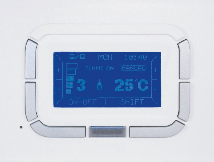
A weekly programmable digital chronothermostat with remote boiler control (OpenTherm® compatible) and remote management via gsm.
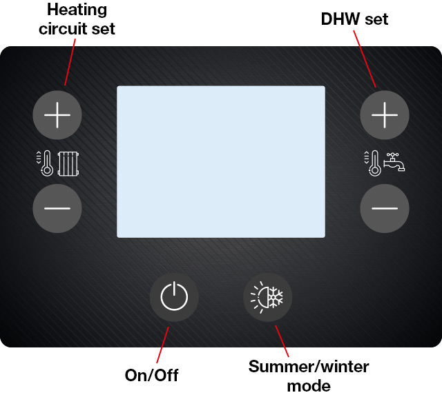
The digital chronothermostat Kronos series integrates the functions of room temperature control and remote control of home heating system in a single interface. Specifically designed for the TI45 Ultra Lean, the functionality is both intuitive and user friendly.
It is possible to choose between different modes of thermoregulation, even when using an external probe for climatic compensation.
Weekly programming is particularly versatile because it provides four settable temperature levels with no restriction on the number of time slots per day. Segmented by quarter of an hour intervals, configuration can viewed on a daily programme graph in the control panel.
The communication between the thermostat and the control board of the boiler takes place by means of a two-wire cable; the data are exchanged with the communication protocol compatible OpenTherm™ v3.0.
| Operating temperature | 0°C + 50°C |
| Power supply | 3V |
| Protection degree | IP30 |
| Dimensions | 140mm x 90mm x 32 mm |
| Weight | 170 g |
| Directive | EMC 2004/1108/CE LVD 2006/95/CE |
| 1 | Room thermostat zone 1 connection (option remote control OPEN THERM) |
| 2 | Room thermostat zone 2 connection (depending on module configuration) |
| 3 | External sensor connection |
| 4 | 50°C safety thermostat connection (low temperature heating circuit) |
| 5 | 2-way valve (heating zone 2) or DHW return pump with scheduling (Excludes by-pass function) |
| 6 | Primary circuit 2-way valve connection |
| 7 | Firmware update serial connection |
| 8 | RS485 connection interface (remote control), external sensor reading, primary circuit main valve settings |
| Error code | Meaning |
|---|---|
| E1.1 | System pressure lower than parameter value P9 |
| E1.2 | System pressure higher than parameter value P10 |
| E2.1 | Primary circuit sensor failure: short circuit |
| E2.2 | Primary circuit sensor failure: open circuit |
| E3.1 | Heating circuit flow sensor: short circuit |
| E3.2 | Heating circuit flow sensor failure: open circuit |
| E4.1 | Domestic water circuit sensor failure: short circuit |
| E4.2 | Domestic water sensor failure: open circuit |
| E5.1 | Heating circuit return sensor failure: short circuit |
| E5.2 | Heating circuit return sensor failure: open circuit |
| E 7 <–> nn | Circulating pump error: the feedback signal notify a malfunction |
| E.8 | Limit thermostat intervention (visualizzato solo con P2 = 1) |
| E.9 | DHW temperature over 60°C |
| E.10 | Eeprom memory failure: replace the circuit board |
| Error code | Description |
|---|---|
| t.1 | Primary circuit sensor temperature [°C] |
| t.2 | Heating flow circuit sensor temperature [°C] |
| t.3 | Heating return circuit sensor temperature [°C] |
| t.4 | DHW sensor temperature [°C] |
| H2o | Heating circuit pressure [bar] |
| FLM | DHW withdrawal [l/min] |
| Pmp | PWM signal value [%] (refer to the graph.1 operating manual) |
| Fb.p | Circulating pump feedback: flowrate [l/min] |
| Stp | Stepper motor position [1 half step = 0,0064mm] in relation to total closure |
| Act | Heating circuit modulating valve working position [msec] |
| t.5 | External sensor temperature [°C] |
| Es.t | Heating circuit setpoint (calculated in function of the outside temperature) [°C] |